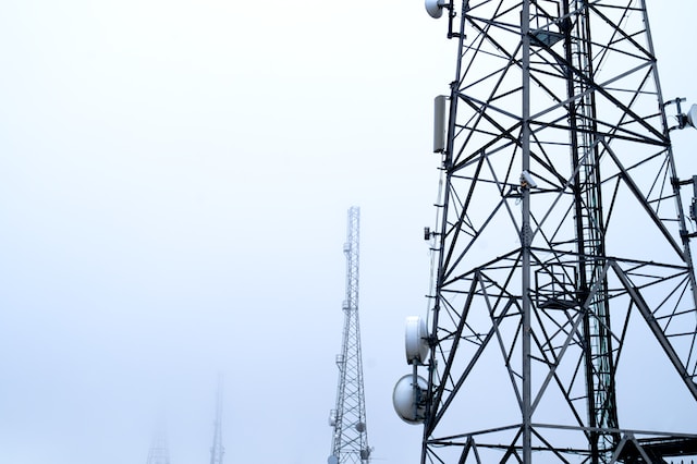


How to solder a 50 MHz radio station with your own hands
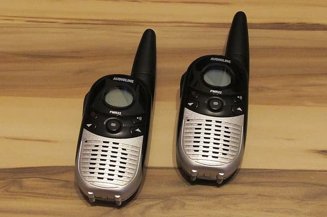
Immediately a warning. If you want to build a cheap radio not for study or experimentation, you are in the wrong place. Immediately buy this LPD or a couple of these radios, for further you will not be interested.
When assembling the radio, you must have experience in soldering components, skills in determining the ratings of components and their installation on circuit boards by soldering. The tools for work are a low-power soldering iron with solder and rosin, wire cutters and a Phillips screwdriver.
The basis of the construction set is a set of JC986A radio parts which includes all needed components (except for the 9V battery) to assemble one radio in the range of radio telephones (frequencies around 49.8MHz). In total it is necessary to assemble at least two radios. All parts of the construction set are shown on the photo. The body is well made, but not of shockproof polystyrene. All of the plastic parts fell into place without any problems. The board withstood all soldering and troubleshooting and the tracks did not flake off. All tracks are covered with flux, soldering was performed without problems. The parts were complete.
Schematic of a simple radio
The radio is controlled by two switches. A floating switch S1 switches the transmit/receive mode of the radio (in the schematic the switch is in the receive mode). Switch S2 supplies power to the radio station. Transistor Q1 operates to receive in the superregenerative receiver circuit. The RF signal to the receiver is fed from the antenna Ant and the coil L1 to the circuit C1T1C4. The reception frequency is mainly determined by this circuit. The resonance frequency of the circuit can be changed with a tuning core. When switching switch S1 to transmit mode the receiver circuit goes to the mode of RF oscillator at the receiving frequency. Transistors Q2-Q5 are used to build a transformerless LF amplifier. In the LF reception mode the receiver signal through the chain R5, C10, C14 goes to the LF input and is amplified. The load of the VLF is the speaker SP. In the transmit mode the speaker is connected by the switch S1 to the capacitor C14 (it becomes a microphone) and the VLF amplifies the signal from the speaker. The load of the LPF is the high-frequency generator which is supplied with alternating voltage from the middle point of the LPF amplifier through the limiting resistor R9. The AC voltage modulates the RF output signal into the antenna. The antenna is connected through an extension coil – choke L1. On the board there are places for three more elements of the tone call when transmitting – R10, C7 and the button (these parts are not included in the kit).
Step-by-step instructions for assembling the radio station with your own hands
Step 1. When you receive the parcel, check the completeness of parts of the case and radio components. Study the markings. Resistor ratings are color-coded. A key to read is included on the page. Do not confuse the L1 choke with the resistors, it is much larger. Smaller parts are best kept in a closed box. Examine the circuit board from the parts side to understand where to mount the parts.
Step 2: Start the soldering process by installing the resistors. Form the electrodes of the resistor. Solder it to the board and cut off the protruding electrodes with wire cutters. This is how we install all the elements with long electrodes. The position of each element is marked on the board. Be careful not to make mistakes. Solder all the resistors one after the other.
Step 3: Solder the extension coil L1.
Step 4: Solder the capacitors.
Step 5. solder the electrolytic capacitors. The elements have the polarity of the installation.
Step 6. solder the circuit coil T1, switch S1. Make sure to solder the metal body of the switch to the board.
Step 7. solder the transistors by strictly following the markings on the board.
Step 8. With the cut off electrodes we solder jumper J1 to the board.
Step 9: Check the correctness and quality of elements installation. You can rinse the board from the flux residue with alcohol. Install the plastic button for switching between transmit and receive. Fix the board to the housing with two self tapping screws.
Step 10. Install antenna. On top of the antenna we put the plastic cap. Solder the connection wire to the board to the lobe of the antenna. Pieces of wire from the parts solder the switch S2. Check the operation of the power switch. The switch lever should move when you rotate the plastic knob.
Step 11: Re-solder the solder wires to the battery compartment terminals. Install the terminals in the battery compartment. Solder the speaker connection wires and the power supply wires from the battery compartment. Observe the polarity! You can insert the battery and, if you are sure that everything is assembled correctly, apply power. You should hear the hiss of the receiver working from the speaker. You can check the operation of the transmitter with the field indicator. Connect the two halves of the case with 5 tapping screws.
Step 10. Assemble the second radio station in the same way. For proper operation, the receiving and transmitting frequencies of each radio must be identical. To do this, the board of one radio station is removed from its fasteners. An improvised dielectric screwdriver with a straight slot is made from a match. We turn on one radio station to receive, the second disassembled one to transmit (the distance between the stations is 1 meter) and by turning the core of the circuit with a wooden screwdriver we achieve a loud sound of the voice on the reception of the first radio station.
Repeat these operations at distances of 5 and 20 meters. It is better to tune up in the open air. Do not forget, radio stations are simple and the signal will be influenced directly close to the antenna objects and signal capture by the receiver may not work. It is very useful to use SDR USB receiver. Watch this video. It will allow you to estimate the signal strength, frequency, frequency stability and quality of modulation. Assemble the case of the second radio station.
This completes the configuration of the radios in this circuit solution. The communication range between the radios in the open area is about 100 meters. But this is not the limit, with appropriate modification or simply by connecting appropriate antennas communication range can easily be several kilometers. If interested in the topic, the author will publish some of the improvements. The station is interesting for its range and amplitude modulation. Interference in your conversations is possible, but unlikely. The radiated power in the radio antenna is less than the limits that require a permit or registration.